Julian Straub
creations and thoughts
Creating Light II
In the initial post on creating light we saw the that the simplest way to generating light is using a LED and a resistor to limit the current through the LED. However, burning energy over a resistor is inaccurate: the current changes as the input voltage changes. A better way to drive a LED is to use a current source. This way we determine exactly the current flowing through the LED independent of the voltage drop over it. Current sources can be built in various ways using, among others, Transistors, OpAmps, and FETs. In the following we explore a transistor-based current source.
Transistor Current Source
The idea is to use a transistor to design a current source. I.e. a circuit that is designed to force a pre-determined current through a load, in our case a LED as shown in the figure below.
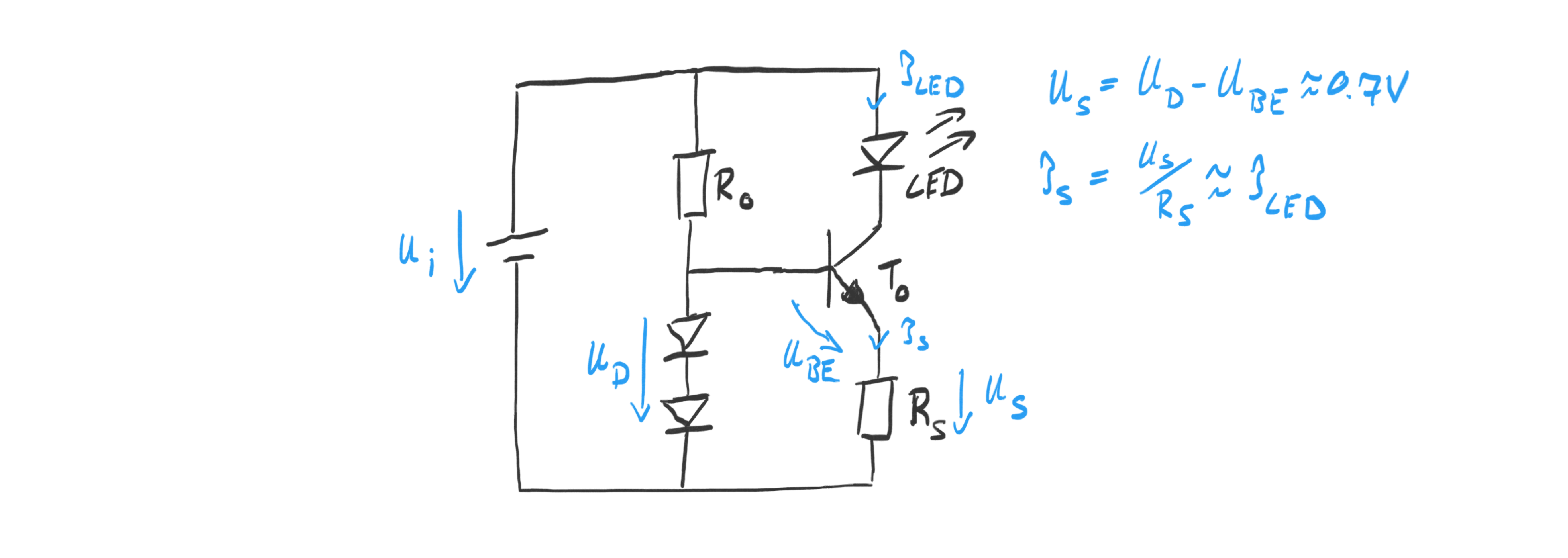
The simplest way is to force a voltage
\(V_D\)
between the base of the transistor and a sensing resistor
\(R_S\)
connected to its emitter. Since the base-emitter voltage
\(V_{BE}\)
is one diode forward drop of about 0.7V, the remainder of the voltage has to drop across the resistor
\(R_S\)
. The transistor adjusts the current flow
\(I_S\)
from collector to the emitter accordingly.
The resistance of
\(R_S\)
in combination with
\(V_D\)
determines the current
\(I_S\)
as
We can force the input voltage to a predefined level using one or multiple LEDs of various kind: we can use N standard diodes (like 1N4108) to get
\(V_D = N \cdot 0.7V\)
, a red LED to get
\(V_D = 2.2V\)
, or a Zener diode to get
\(V_D = V_{Zener}\)
.
It is a good idea to keep the voltage drop over the sensing resistor small since it takes away from the voltage that can be used to drive the desired current through the load LED. A simple variant uses two standard diodes in series to achieve
\(V_D = 1.4V\)
. Then
For a common LED current of I = 20mA the resistor would have to have
\(R_S = 35 \Omega\)
. Note that since the voltage drop is small, a standard 1/4W resistor can be used. The resistor
\(R_0\)
needs to allow sufficient current to saturate the diodes and the base of the transistor. A current of 1mA should be sufficient.
Thoughts and comments
- In the transistor-based current source the remaining energy is “burned” over
the transistor and not, like in the simple resistor-based approach, the resistor.
This means the only advantage is that the LED will burn at constant brightness
as long as the input voltage is big enough (
\(> U_S + U_{LED} + U_{CEmin}\)
, where \(U_{CEmin}\approx 0.2V\)
).