Julian Straub
creations and thoughts
Harvesting Light
Light emitted from the sun is the basis of most live on earth (with the exception of creatures living of of deep sea thermal vents). Light gets harvested by plants, which are then consumed by the animals that are first in the food chain for other animals. Through coal, oil and natural gas, much of the energy sources for human kind are also dependent on solar energy stored millions of years ago in plants.
Harvesting light therefore is the most basic building block for our ecosystem and it is fascinating to think about the amazing potential of a non-photosynthesis alternative: solar cells. Solar cells directly convert incoming light into electrical power. A single solar cell generates a voltage of up to 0.6V and a current that is dependent on the area of the cell. Multiple cells can be arrayed to produce higher voltages and higher currents. Solar farms are just huge arrays of individual cells wired together.
Here I am interest in building small systems that harvest light to do simple things like emitting light via a light emitting diode (LED) or turning a motor. I am exploring various ways to harvest light that are inspired by the designs of solar engines from BEAM robotics.
Light Harvester 0 – Harvest and Emit Light
The first kind of solar harvester, collects light until its storage is full and then releases the energy over a load circuit, i.e. a LED.
The circuit shown below operates in two states: charging and energy release.
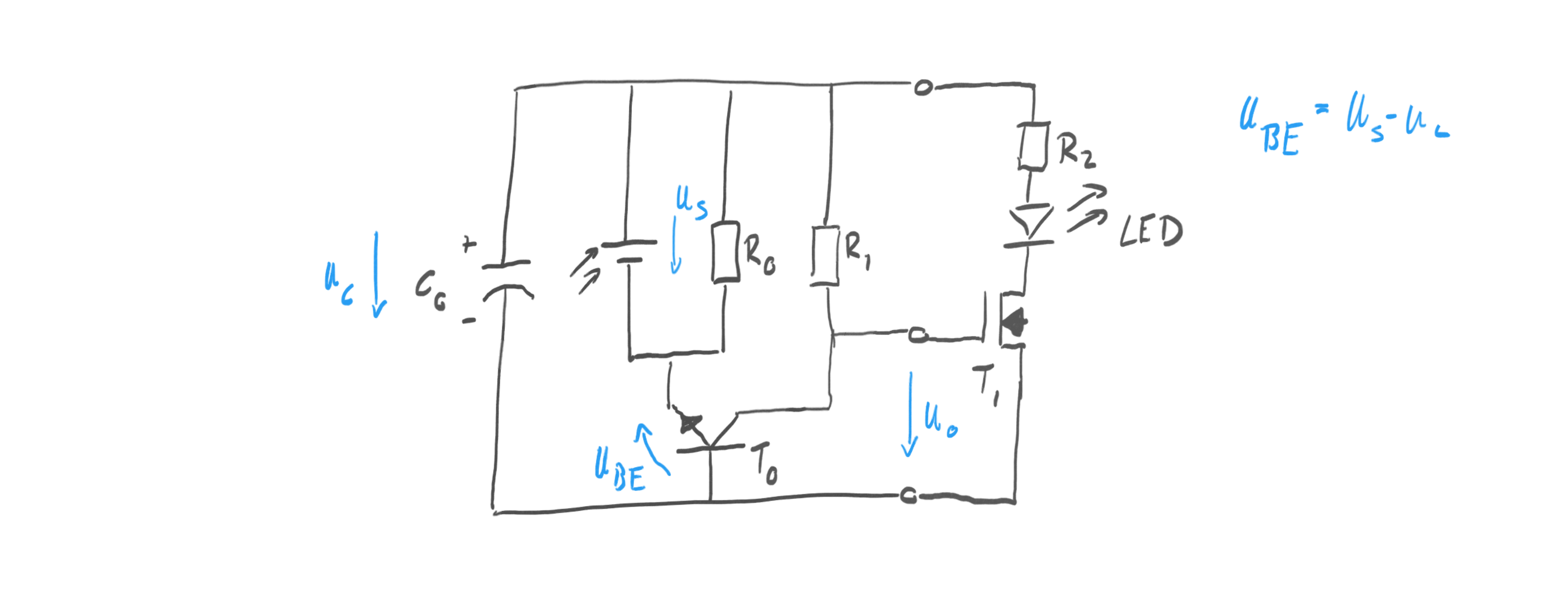
During charging the voltage from the solar cell U_s is larger than the voltage on the capacitor
\(U_c\)
.
In this case
\(U_{BE} > 0\)
. As long as
\(U_{BE} > 0.7V\)
, the usual forward drop of the base-emitter junction in transistor
\(T_0\)
,
\(T_0\)
is in saturation and the capacitor is charging.
Since
\(T_0\)
is saturated, the output is pulled to the same potential as the negative terminal of the solar cell. Hence, the voltage
\(U_o = -U_{BE} \approx -0.7V\)
. This ensures that the MOSFET
\(T_1\)
is turned off. No current can flow through the LED during charging phase.
The resistor
\(R_0\)
is chosen to be large
\(> 1M\Omega\)
. This means during charging a small but negligible current flows through it. Similarly the resistor
\(R_1\)
is a large (
\(\approx 1M\Omega\)
) pull-up resistor that leaks a small amount of current through
\(T_0\)
but does not change the output voltage during charging. The importance of
\(R_0\)
and
\(R_1\)
only become clear during the release phase.
During energy release the voltage
\(U_s\)
of the solar cell drops below the capacitor voltage
\(U_c\)
so that
\(U_{BE} < 0V\)
.
This turns off
\(T_0\)
, allowing the pull-up resistor
\(R_1\)
to pull up
\(U_o\)
to the positive potential of the capacitor making
\(U_o = U_c\)
. This charges the gate of
\(T_1\)
and turns on the MOSFET. Hence the capacitor can discharge over the resistor and the LED to convert the stored solar energy back into light.
\(R_0\)
determines the onset of energy release: as incident light on the solar cell decreases, can deliver less and less current and eventually the load of
\(R_0\)
is enough to pull
\(U_s\)
below
\(U_c\)
. This starts the energy release.
As the capacitor is discharging over the LED, its voltage drops, eventually falling below the forward voltage of the LED (here 1.4V of a red LED). This stops discharging.
Importantly, the circuit cannot release all charge over the LED because of the forward voltage of it.
The other limitation of the circuit is that the capacitor can only be charged to
\(U_c \leq max(U_s)-0.7V\)
.
Thoughts and considerations:
- Depending on
\(R_0\)
, it starts discharging when its still pretty bright in the room. In the latest built I am using \(R_0 = 5.6M \Omega\)
and it still turns on quite early.
- The capacitor can only be charged to
\(U_s - 0.7V \)
which works out quite well with a 6V solar cell and 5.5V super capacitors.
- Discharging through a LED with a current-limiting resistor as shown above has two problems (1) energy is “burned” over the resistor and not converted into light and (2) the forward voltage of the LED limits how low the capacitor can be discharged. It means there is always some residual charge left that is not used.