Julian Straub
creations and thoughts
Harvesting Light II - Blinker with Charge Pump
Building the pretty straight forward light harvester described in a previous post, I learned that that design is somewhat passive: the harvester just charges the whole day and then discharges for 1-2h (depending on the capacitor) once it gets dark.
To explore a more active harvester that periodically emits energy whenever the capacitor is charged, I reimplemented the
VxSE3 solar engine by WLF Rigter:
 Reproduced here with my specific adaptations:
- used a green LED with forward voltage of 3.2V
- a solar panel with 3V output (max 4V)
-
\(10\mu F\)
storage capacitors
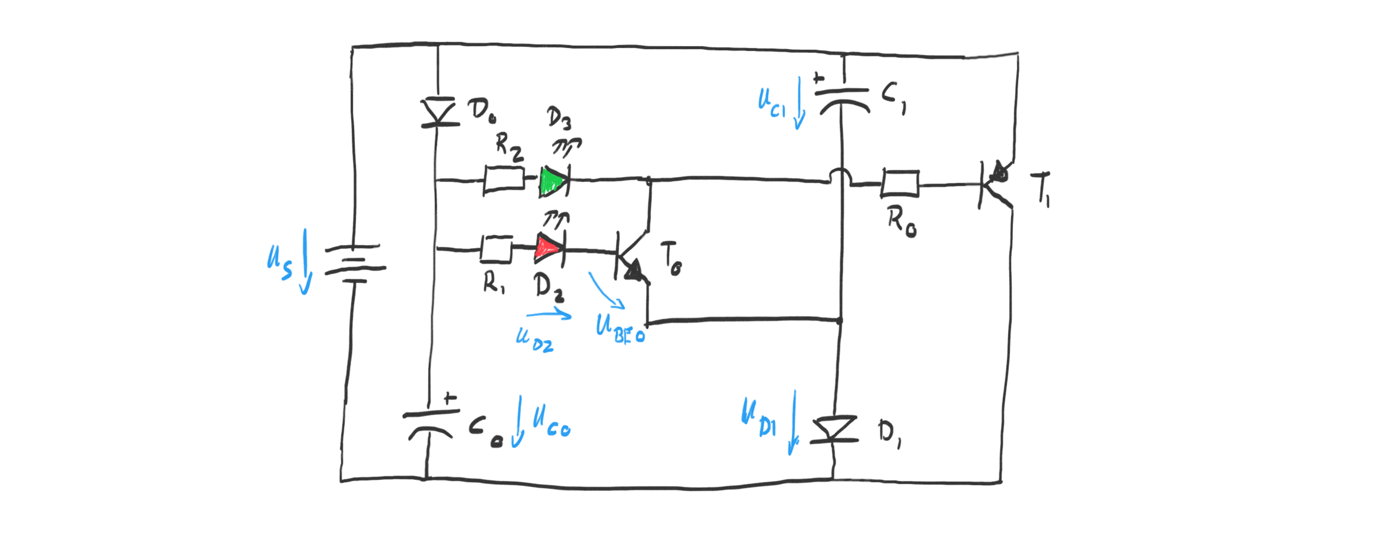 The circuit above is pretty clear for the charging cycle: the capacitors are charged in parallel each through its own diode. I used Schottky diodes with a forward drop of 0.4V.
Given the 3V solar cell this means they will each be charged to about
\(U_{c0} = U_{c1} = 2.6V\)
The circuit above is pretty clear for the charging cycle: the capacitors are charged in parallel each through its own diode. I used Schottky diodes with a forward drop of 0.4V.
Given the 3V solar cell this means they will each be charged to about
\(U_{c0} = U_{c1} = 2.6V\)
.
Once the capacitors reach their full charge the transistor
\(T_0\)
goes into conduction. We can see that by looking at the voltage
\(U_{BE0}\)
:
which is
\(>0.7V\)
since the resistor just acts to limit the current into the transistor.
With
\(T_0\)
saturated and in conduction it is instructive to look at this re-drawing of the circuit to understand the voltage doubling feature of this circuit:
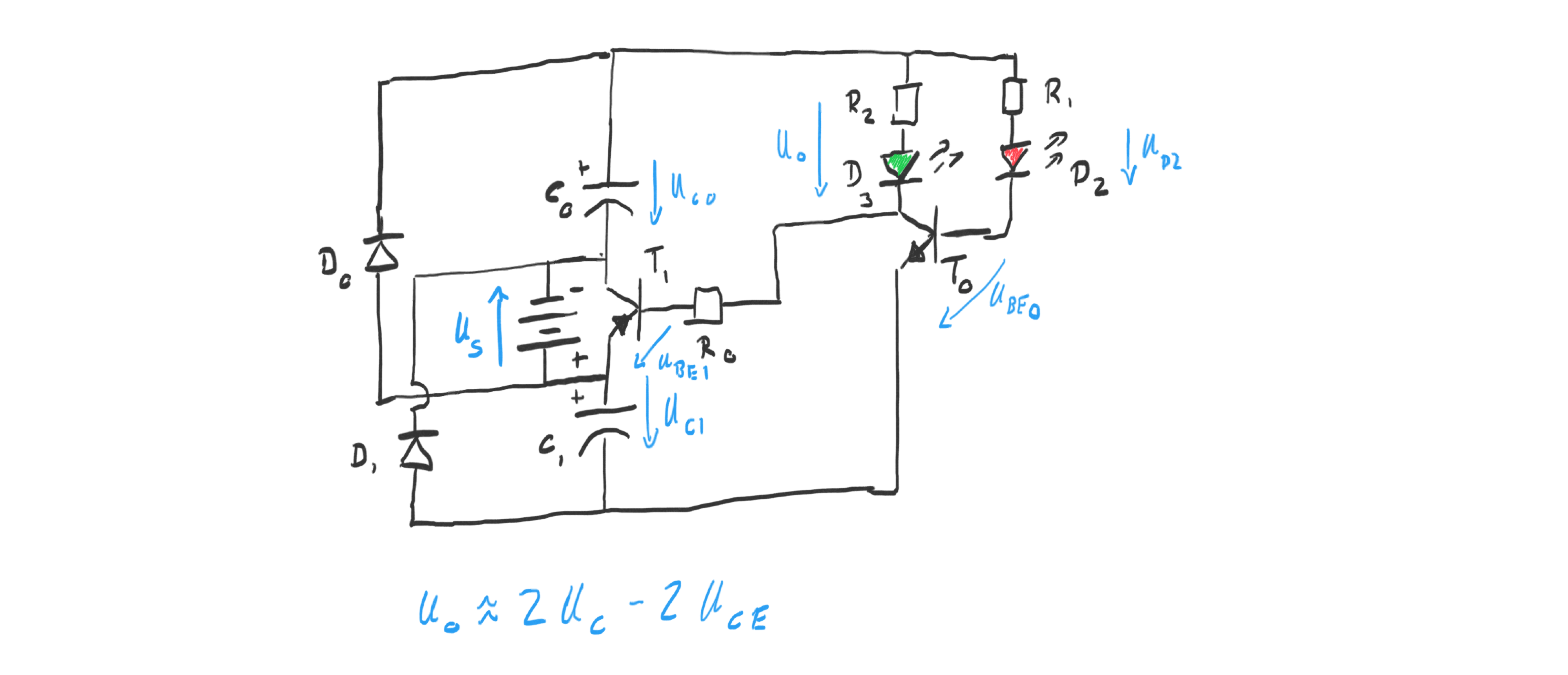
As soon as
\(T_0\)
is in conduction, the output of the green LED
\(D_3\)
is pulled to the potential of the lower capacitor
\(C_1\)
. The base of the pnp transistor
\(T_1\)
is pulled to the same potential as well. The saturates
\(T_1\)
as can be seen from the base-emitter voltage of
\(T_1\)
:
The saturated npn transistor
\(T_1\)
then connects the two capacitors leading to an approximate doubling of the input voltage. More precisely, the following voltage is applied over the green LED and its resistor:
This doubling of the voltage reminds of a charge pump circuit.
The resistor
\(R_2\)
limits the discharge current through the green LED
\(D_3\)
as usual, in the most simple LED circuit. As the capacitors discharge the voltage eventually drops too low to keep transistor
\(T_0\)
in conduction and the circuit resets to charging mode.
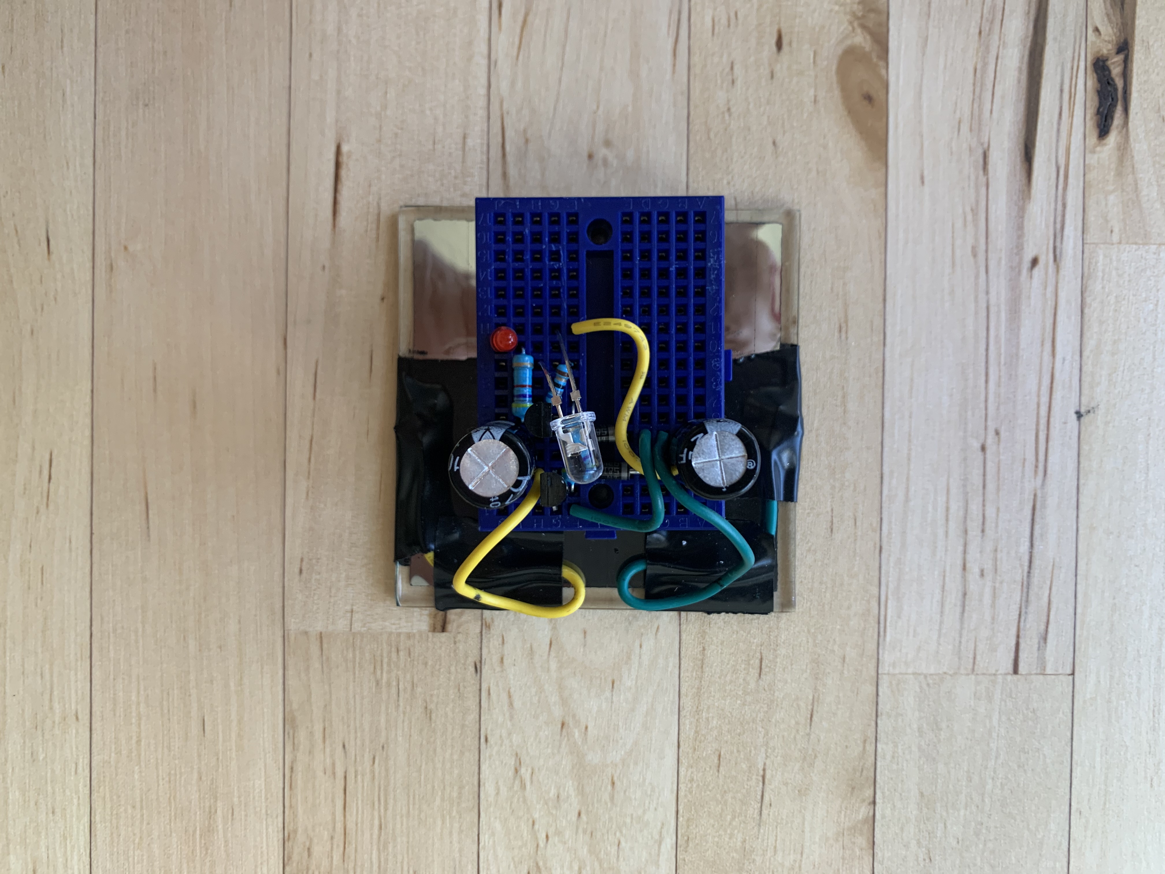
The initial version used the parts as described in the original engine:
-
\(R_0=4.7k\Omega, R_1=4.7k\Omega, R_2=68\Omega, C_0=C_1=1mF\)
.
-
\(D_0=D_1=\)
Schottky
-
\(T_0=\)
2N3904 and \(T_1=\)
2N3906
-
\(D_2=\)
low power red LED
-
\(D_3=\)
one ultra-bright green LED.
- 4V max - rated for 3V solar cell.