Julian Straub
creations and thoughts
Analog Solar Cell Voltage Stabilizer for Maximum Power Output
Solar cells are non-ideal power sources that need managing in order to derive maximum power from them. The one of the reasons are the non-negligible series and parallel resistance in solar cells. The I-U and I-P plot of a solar cell shown below illustrates the point: we have to regulate the voltage or current drawn from the solar cell in order to reach a point of high power output. The maximum is called maximum power point (MPP).

Maximum power point trackers (MPPT) are a complex topic in themselves and
important for high-power solar cell modules where efficiency is important. For
smaller applications of for example charging a battery from a small module
adafruit argues that ensuring a fixed solar-cell voltage is good
enough.
In their design of a solar-cell battery charger, they ensure that the solar cell
voltage stays at about
\(0.45V\)
per cell via the charging IC directly.
I was wondering how to stabilize the solar cell voltage close to the MPP in the
simplest way for the use in light harvesters.
The analog solar cell voltage stabilizer depicted in the circuit below regulates
the output current such that the input voltage
\(U_I\)
stays at a fixed voltage
programmed via the voltage divider. This lets us then choose an input voltage
close to the MPP of the solar cell.
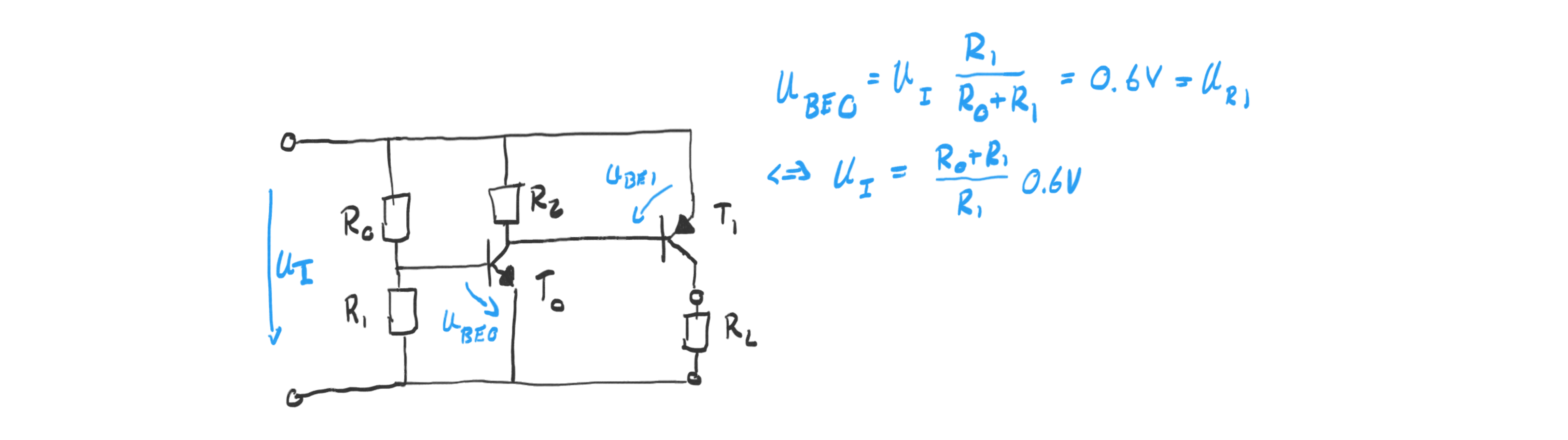
Specifically, the voltage
\(U_{R1}\)
over resistor
\(R_1\)
is held fixed at the base
emitter voltage of
\(T_0\)
of roughly
\(0.6V\)
.
We can examine the workings of the regulator by imagining two states: (1) the
input voltage is lower than the desired voltage and (2) the input voltage is
higher. In case (1), the voltage over
\(R_1\)
is lower than
\(0.6V\)
closing
transistor
\(T_0\)
. This leads to a decrease of the voltage over the pnp
transistor
\(T_1\)
bases emitter voltage because of the pull-up resistor
\(R_2\)
.
\(T_1\)
also starts closing and hence reducing the flow of current
\(I_o\)
into the
load. The decreasing demand on current from the solar cell increases its voltage
output according to the operating characteristics of a solar cell shown in the
I-U plot in the beginning.
In the case (2) of higher-than-desired input voltage, the behavior of the
regulator is the inverse: the output current is increased which leads to a
decrease of the input voltage.
The voltage over
\(R_1\)
and hence
\(U_{BE0}\)
of npn transistor
\(T_0\)
is greater
than
\(0.6V\)
and hence opens
\(T_0\)
completely. This pulls down the base of pnp
transistor
\(T_1\)
so that
\(T_1\)
also goes into saturation and hence increases the
current flow into the load.
Note, that the analog input voltage stabilizer is low drop out (LDO): when the
output transistor
\(T_1\)
is fully open the minimum voltage drop and hence
“wasted” energy of the stabilizer is only the collector-emitter voltage of the
pnp transistor during saturation which is usually given as less than
\(0.2V\)
.
From published work (see above) and an article from
adafruit
it seems like the maximum power point per solar cell is between
\(0.5V\)
and
\(0.45V\)
. This means for a
\(6V\)
solar cell array (of 10 cells) the maximum power
point is between
\(4.5V\)
and
\(5\)
. We can set this input voltage using the analog
voltage stabilizer by the following choice of parts:
-
\(R_0=7.5k\Omega\)
, \(R_1=47k\Omega\)
, \(R_2=10k\Omega\)
-
\(T_0\)
is a 2N3904 npn, \(T_1\)
is a 2N3906 pnp transistor