Julian Straub
creations and thoughts
Stand-alone Arduino EEPROM Voltage Logger
The arduino voltage logger from the previous post worked by directly sending all voltage values to a computer for logging. This way storage is virtually limitless. The downside, of course, is that the computer needs to be sitting right with the arduino for as long as the logging is desired. This is limiting when you actually want to use the computer for other things during logging or if the place where you need to log the voltage is in a weird location where its hard to put a laptop or computer.
For these reasons, I upgraded the arduino voltage logger to be stand-alone by logging to the internal EEPROM memory. You can find all code on my github.
The code implements a small state machine that erases and starts logging upon a button press. Values are logged at a fixed frequency specified in the main. While reading and writing is quite straight forward with the built in commands, the internal EEPROM of 1kb is quite limited. Therefore, I implemented a delta encoder which encodes a series of values as the difference to the previous value. Since the differences are usually small (for the applications I had in mind), we can encode them as signed int8_t values which take up only half the space of the uin16_t ADC values:
void InitDeltaEncoder(struct DeltaEncoder* del, int32_t sum0) {
  del->sum = sum0;
}

int8_t UpdateDelta(struct DeltaEncoder* del, uint16_t cur) {
  // compute delta between current value and running sum
  int32_t delta = (int32_t)cur - del->sum;
  // truncate delta to +- 127 so it fints insight int8_t
  int8_t delta8 = 0;
  if (delta < -127) {
    delta8 = (int8_t)-127;
  } else if (delta > 127) {
    delta8 = (int8_t)127;
  } else {
    delta8 = (int8_t) delta;
  }
  del->sum += (int32_t)delta8; // keep track of running sum
  return delta8;
}
The initial value for each time series is still written in full to the EEPROM right at the start. After that only differences are logged.
This means the logger can log 510 adc values into the internal EEPROM.
Logging every
\(24\cdot 3600s / 510 = 167s\)
we can log for a full 24h.
The other feature I added to this logger is a ring buffer to enable filtering of the measured voltages. The ring buffer always contains the last 60 measured values.
struct RingBuffer {
  uint16_t data[60];  // data in the buffer
  uint16_t N;         // size of the buffer - initialized to 60
  uint16_t i;         // current position in the buffer
};

void Insert(struct RingBuffer* buf, uint16_t x) {
  buf->i = (buf->i + 1) % buf->N; // wrap around index after incrementing
  buf->data[buf->i] = x;          // insert new value
}
From that we can at any moment compute the mean ADC value over the last minute:
float MeanFloat(struct RingBuffer* buf) {
  float sum = 0;
  for (uint16_t i=0; i< buf->N; ++i) {
    sum += buf->data[i];
  }
  return sum / (float)buf->N;
}
The code given here is slightly simplified for presentation purposes (it does not handle the inital phase when not all 60 values are filled—see the code on github for that). This nicely smoothes out some of the measurement noise and makes use of the fact that while we cannot log values at a high frequency because of the EEPROM memory limitations, the arduino can itself de-noise the input signal by sampling at a higher frequency.
After logging is done, i.e. the EEPROM memory is full, as indicated by the onboard LED turning off, one just needs to connect the arduino to the computer and it will send the measured series of voltages at the two ADC pins. These can be received as described before and plotted. Below is an example of logging the voltage at the capacitor (adc0) and the output (adc1) of the night-active light harvester.
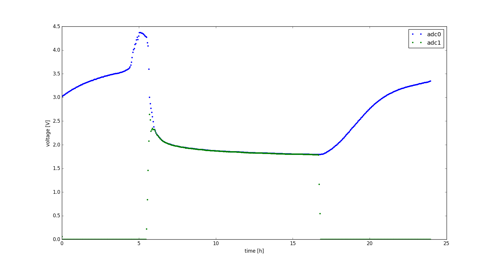
You can see that the logged voltages are nice and smooth thanks to the ring-buffer-based filter.